
- Home
- Products
- Solutions
- About
- Service
- Sustainability
- News
- Contact Us

Views: 0 Author: Site Editor Publish Time: 2026-07-12 Origin: Site


Upgrading or replacing the hot zone insulation in a vacuum or inert gas furnace represents a high-stakes engineering decision. Incorrect material selection leads directly to thermal inefficiencies. It can also cause product contamination or premature structural degradation. Ceramic and metallic shields certainly serve specific purposes in lower-temperature applications. However, carbon-based insulation remains the absolute standard for extreme environments operating between 1000°C and 3000°C.
The core challenge lies in matching complex material properties to your distinct thermal processing requirements. This comprehensive guide breaks down how you can effectively evaluate, shortlist, and select the exact Graphite Insulation Material required for your application. We will explore structural form factors, precursor materials, and critical selection dimensions. You will learn to balance initial material characteristics against long-term operational reliability. Properly specified hot zones maximize energy efficiency and protect your valuable workloads.
Form Factor Dictates Function: Rigid graphite boards offer structural stability for high-velocity gas quenching, while soft graphite felts provide superior cost-to-insulation ratios for static vacuum environments.
Precursor Materials Matter: Choosing between PAN-based and Rayon-based graphite insulation directly impacts thermal conductivity, ash content, and structural longevity.
Process Matching is Critical: Final selection must be mapped to your furnace’s specific operating temperature, atmospheric conditions (vacuum level/gas type), and purity requirements.
Soft felt and rigid boards represent the two primary structural options available today. You must choose the right physical format based on your chamber's atmospheric turbulence. Evaluating these formats properly prevents catastrophic structural failures during operation.
Soft felt arrives in highly flexible, continuous rolls. It costs significantly less than rigid alternatives during the initial purchase. It traps heat efficiently because it features an incredibly low bulk density. Standard vacuum furnaces benefit immensely from this material. You should specify soft felt for continuous processing applications. It works perfectly when gas flow velocity remains low. The lack of structural rigidity does not matter in entirely static environments. Maintenance teams can easily cut it to fit complex chamber geometries.
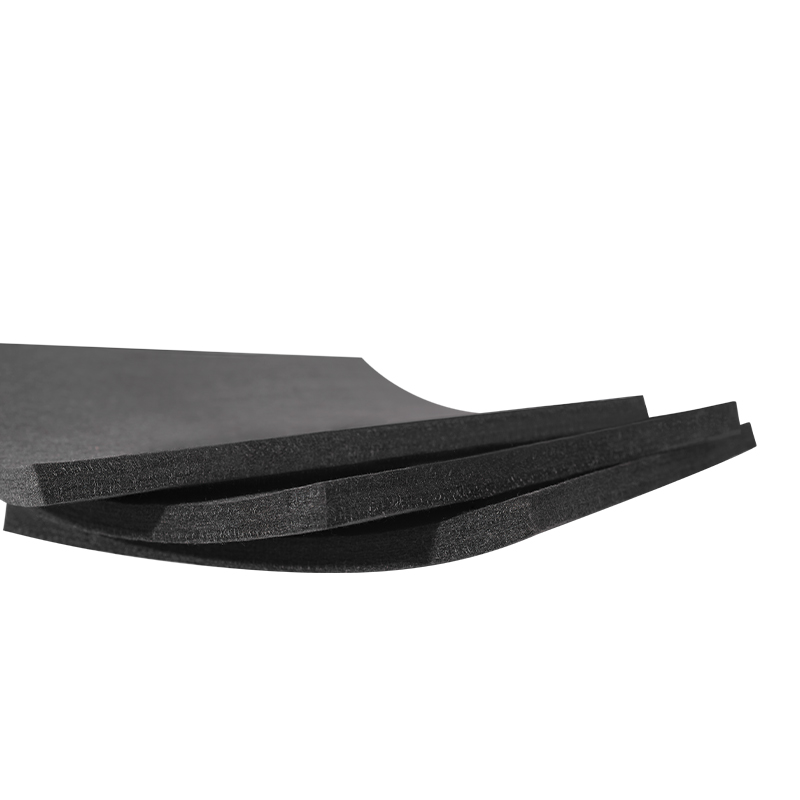
Manufacturers build rigid boards using multiple layers of soft felt. They bond these layers using specialized carbon resins. The factory then cures these composites into solid panels or large cylinders. Suppliers often face these rigid boards using CFC (Carbon-Fiber Composite) sheets or pure graphite foil. You need rigid structures for high-pressure gas quenching environments. They resist physical erosion during turbulent, high-velocity cooling cycles. You also gain extreme dimensional stability. Applications highly sensitive to particulate shedding rely on rigid structures. The solid facings lock loose fibers away from your workload securely.
Many modern facilities currently transition from traditional solid graphite blocks to hybrid rigid felt systems. Solid graphite blocks hold massive amounts of thermal energy. Hybrid rigid boards offer a much lower thermal mass. This structural change allows your furnace to execute significantly faster heating and cooling cycles. You directly reduce energy consumption during each batch run. We see operators upgrading older hot zones routinely to capture these efficiency gains. It modernizes legacy equipment efficiently.
Manufacturers produce carbon fibers from two distinct precursor polymers. You must choose between PAN (Polyacrylonitrile) and Rayon strictly based on your application needs. Understanding this chemical origin helps you predict long-term material behavior.
PAN represents the undisputed modern industry standard. It delivers exceptionally high tensile strength and superior oxidation resistance. Heat moves slower through PAN fibers at ultra-high temperatures. This lower thermal conductivity traps energy inside your hot zone highly effectively. Most standard heat treatment and powder metallurgy sintering furnaces rely on PAN. We strongly recommend it for general metallurgical processing. It survives harsh industrial cycles better than any alternative.
Rayon delivers exceptional chemical purity right out of the factory. It produces minimal ash content naturally. It also exhibits extremely low outgassing properties under deep vacuum conditions. However, Rayon fibers feel noticeably softer. They tend to act more brittle than PAN fibers. You must handle them very carefully during installation. Semiconductor manufacturing demands Rayon insulation exclusively. Crystal pulling operations, like the Czochralski process, also require it. Specialized aerospace applications use Rayon whenever micro-contamination causes critical component failures.
You must justify the significant cost premium of high-purity Rayon. Standard hardening and tempering processes rarely need this intense level of trace metal control. PAN provides highly durable, cost-effective performance for most commercial operators. Review the comparison below to guide your precursor selection.
Precursor Material Comparison Chart
Property Metric | PAN-Based Fiber | Rayon-Based Fiber |
|---|---|---|
Tensile Strength | High (Structurally Robust) | Low (Prone to Breakage) |
Thermal Conductivity | Lower at extreme temps | Slightly higher overall |
Ash Content / Purity | Standard Commercial Grade | Exceptionally Low (Ultra-Pure) |
Primary Applications | General Heat Treatment, Brazing | Semiconductors, Aerospace |
You must evaluate four specific performance dimensions before placing a purchase order. These interrelated factors dictate exactly how your material behaves under extreme thermal stress. Ignoring any single dimension compromises your entire hot zone design.
First, evaluate material performance strictly in vacuum or inert gas environments. Nitrogen and Argon atmospheres work exceptionally well. However, you face a catastrophic risk factor regarding oxygen exposure. Graphite Insulation Material oxidizes aggressively above 400°C if exposed to ambient air. You must ensure perfect atmospheric integrity. Minor chamber door leaks will destroy your hot zone rapidly. The carbon simply burns away into carbon dioxide gas. Always map your maximum operating temperature against your specific gas type.
Residual trace metals remain trapped inside standard carbon products as ash. This ash can vaporize at high temperatures and react negatively. Sensitive metallurgical processes, like processing titanium alloys, cannot tolerate these volatile impurities. You must specify "purified" graphite components for highly critical loads. Advanced suppliers can reduce ash content below 20 ppm. Some even achieve below 5 ppm using halogen purification. This high-purity grade prevents disastrous chemical reactions inside your chamber.
Density and fiber orientation directly affect overall heat retention. Heat travels differently along the fiber axis versus across it. You must match the insulation’s thermal mass to your target cycle speeds. Lighter materials allow rapid ramp-up and cool-down speeds. Denser configurations hold heat longer for highly stable soaking periods. Engineers carefully calculate required thicknesses based on these specific conductivity curves. An oversized hot zone wastes massive amounts of electricity.
Bare felt sheds microscopic carbon fibers easily into the chamber. Graphite foil or CFC facings solve this dusting problem completely. These protective surface layers also reflect radiant heat back toward the center workload. Facings physically block high-velocity quenching gas from penetrating and eroding the soft internal fibers. We highly recommend facing your rigid boards for maximum longevity. Unfaced boards simply do not survive aggressive gas cooling.
You must plan for practical installation procedures and operational maintenance requirements. Proper commissioning determines the ultimate success of your insulation upgrade. Poor installation destroys even the highest quality materials rapidly.
Every new hot zone requires dedicated initial bake-out cycles. The manufacturing process leaves residual chemical volatiles trapped inside the carbon matrix. Fibers also absorb atmospheric moisture heavily during shipping and storage. You must execute proper outgassing routines before running real production workloads. Slowly ramp up the temperature under high vacuum conditions. Hold the temperature at specific intervals. This purges moisture safely and prevents immediate contamination of your first product batches.
Soft and rigid formats require completely different mechanical installation techniques. Rigid boards demand precise machining and tight tolerances. You must fit joints tightly to prevent radiant heat leaks from escaping. Staggered lap joints often provide the best thermal seal. Soft felts require careful manual stretching and tensioning. Technicians use specialized graphite lacing cords to tie felts into place. Improper tension causes soft felts to sag severely over time. Sagging creates dangerous cold spots inside your furnace chamber.
Carbon fibers naturally shrink over hundreds of harsh thermal cycles. You must anticipate this dimensional change during the engineering design phase. Physical erosion from high-velocity quenching also degrades protective facings gradually. Operators should plan for a standard three-to-five-year hot zone replacement cycle. Monitor your heating efficiency closely every month. When your furnace requires significantly more electrical power to maintain its set temperature, severe structural degradation has occurred.
You need a structured, logical approach to finalize your material choice safely. Follow these four specific steps to guarantee total technical alignment between your equipment and your new materials.
Step 1: Audit the Current Hot Zone. Identify the exact primary failure mode of your existing insulation. Look for obvious gas erosion, structural sagging, chemical contamination, or rising thermal inefficiency. This baseline data guides your upgrade path.
Step 2: Map to Process Parameters. Document your absolute maximum operating temperature accurately. Record your deepest required vacuum levels and highest gas quench pressures. Note any specific workload sensitivities regarding carbon dust or trace metals.
Step 3: Define Form and Precursor. Select between rigid boards or soft felts strictly based on gas turbulence. Choose between standard PAN or ultra-pure Rayon based entirely on your baseline purity audit. Do not over-specify purity unless absolutely necessary.
Step 4: Request Technical Specs. Ask your suppliers for verified thermal conductivity curves across various temperatures. Demand certified ash content documents. Ensure they provide strict dimensional tolerance guarantees for any pre-machined parts.
Selecting your internal furnace materials requires strict engineering discipline. It is never a generic commodity purchase. Assess your atmospheric conditions rigorously before installing new carbon shields. Match the physical rigidity of your panels to your actual quenching gas velocities. Specify purified Rayon fibers only when micro-contamination poses a true failure risk to your specific product. Finally, always execute slow, controlled bake-out cycles to safely remove trapped moisture.
You should consult directly with a qualified thermal engineering specialist today. Ask them to audit your current hot zone for unseen heat leaks. Request specific material samples to test inside your operating chamber. Secure a custom technical quote tailored precisely to your unique furnace dimensions and exact process requirements.
A: These advanced materials handle extreme heat exceptionally well. You can operate them safely up to 2200°C in standard vacuum environments. If you utilize purely inert atmospheres like Argon, maximum performance extends up to 3000°C. However, you must ensure zero oxygen exposure above 400°C to prevent immediate and aggressive structural oxidation.
A: Premature degradation usually stems from three common operational culprits. Micro-leaks in your chamber introduce destructive oxygen during high-temperature cycles. Water vapor outgassing heavily from improperly dried workloads also attacks the carbon matrix chemically. Finally, physical erosion occurs when high-velocity cooling gas tears unprotected fibers away from the main structure.
A: You cannot swap these materials universally. Ceramic fiber thrives in oxidizing atmospheres where oxygen flows freely. Conversely, Graphite Insulation Material is strictly engineered for deep vacuum or purely inert atmospheres. If you place carbon fibers into an oxygen-rich environment at high temperatures, they will completely burn away into gas.
A: Soft felt arrives in flexible rolls. This makes it highly cost-effective for static vacuum furnaces without high gas flow. Technicians tie it into place using carbon cords. Rigid felt bonds these soft layers together using carbon resins to form solid boards. These boards withstand high-pressure gas quenching without losing their physical integrity.


