
- Home
- Products
- Solutions
- About
- Service
- Sustainability
- News
- Contact Us

Views: 0 Author: Site Editor Publish Time: 2026-10-22 Origin: Site


Graphite serves as a foundational material for high-temperature manufacturing and semiconductor production. However, its unique physical properties create severe fabrication challenges. Graphite’s inherent brittleness makes edge chipping a primary risk during fabrication. This directly impacts scrap rates, production costs, and component performance. When edges fracture unexpectedly, entire batches fail strict quality inspections.
Controlling chipping requires a systemic approach. You must balance tool selection, optimize tool paths, and maintain strict environmental controls. This ensures exacting tolerances without sacrificing raw material. We designed this guide to provide engineering and procurement teams with a transparent framework. You will learn to evaluate graphite machining processes effectively from the ground up. Finally, we will help you assess potential manufacturing partners to guarantee precision on your next project. By understanding these root variables, your team can avoid costly production delays entirely.
Understanding edge chipping begins at the molecular level. Many engineers confuse material hardness with brittleness. Graphite is relatively soft, meaning it machines easily compared to hardened steel. However, it lacks ductility. Brittle materials cannot absorb mechanical stress by bending or deforming. Instead, they fracture. This distinct lack of elasticity makes vulnerable geometric features prone to snapping under cutting pressure.
The specific grade of graphite heavily influences chipping risks. Extruded graphite possesses larger grain sizes and inconsistent internal structures. These large grains create natural weak points along edges. In contrast, isostatically pressed graphite features ultra-fine, tightly packed grains. This uniform microstructure supports sharp edges and intricate details significantly better. When you specify materials, selecting an ultra-fine isotropic grade drastically reduces baseline chipping probability.
Edge chipping rarely happens randomly. It usually results from a predictable wear-to-chip pipeline. Graphite dust functions as a highly abrasive compound. As the cutting tool moves through the material, this abrasive dust constantly grinds against the tool edges. Standard cutting edges wear down at an accelerated rate.
Once a tool loses its razor-sharp geometry, its cutting mechanics change entirely. A dull tool no longer shears the material cleanly. Instead, it pushes outward against the graphite structure. Because graphite remains highly brittle, it cannot withstand this compressive pushing force. The material fractures along the edge grain, resulting in a sudden blowout or visible chip.
Mechanical instability further exacerbates structural fractures. Machining generates immense forces. If you use inadequate workholding, the raw material flexes microscopically. Improper spindle speeds also generate resonant frequencies inside the machine spindle. We call this phenomenon chatter.
Chatter introduces rapid micro-vibrations into the cutting zone. These vibrations act like tiny hammer strikes against the fragile graphite walls. Even if you use brand-new tooling, these uncontrolled vibrations will shatter thin walls and delicate corner radii instantly. Securing the workpiece rigidly eliminates this risk.
Achieving flawless results in precision graphite fabrication depends entirely on your tooling strategy. Attempting to cut corners on tool expenses usually multiplies raw material scrap costs. You must view tooling as a critical investment rather than a disposable commodity.
Many machine shops attempt to use standard solid carbide end mills for graphite. Solid carbide proves insufficient for anything beyond short prototype runs. The abrasive graphite powder degrades carbide edges within minutes of continuous cutting. As we established, worn edges directly cause chipping.
To prevent edge failure, diamond-coated and solid Polycrystalline Diamond (PCD) tooling serve as the industry standards. PCD features synthetic diamond particles fused under extreme heat and pressure. This creates an incredibly hard, abrasion-resistant cutting surface. While PCD tools cost significantly more upfront, they maintain their sharp shearing geometry exponentially longer. This sustained sharpness prevents the compressive forces responsible for chipping.
Tool geometry dictates how efficiently the machine evacuates dust. Standard metal-cutting tools often feature five or six flutes. Using these on graphite causes catastrophic failure. Graphite produces powder rather than continuous chips.
You need specific geometric configurations:
Even PCD tools eventually wear down. Managing their lifecycle requires strict discipline. If you wait until you see visible wear on the cutting edge, you have already compromised the graphite part. Implementing a strict management framework guarantees zero-defect runs.
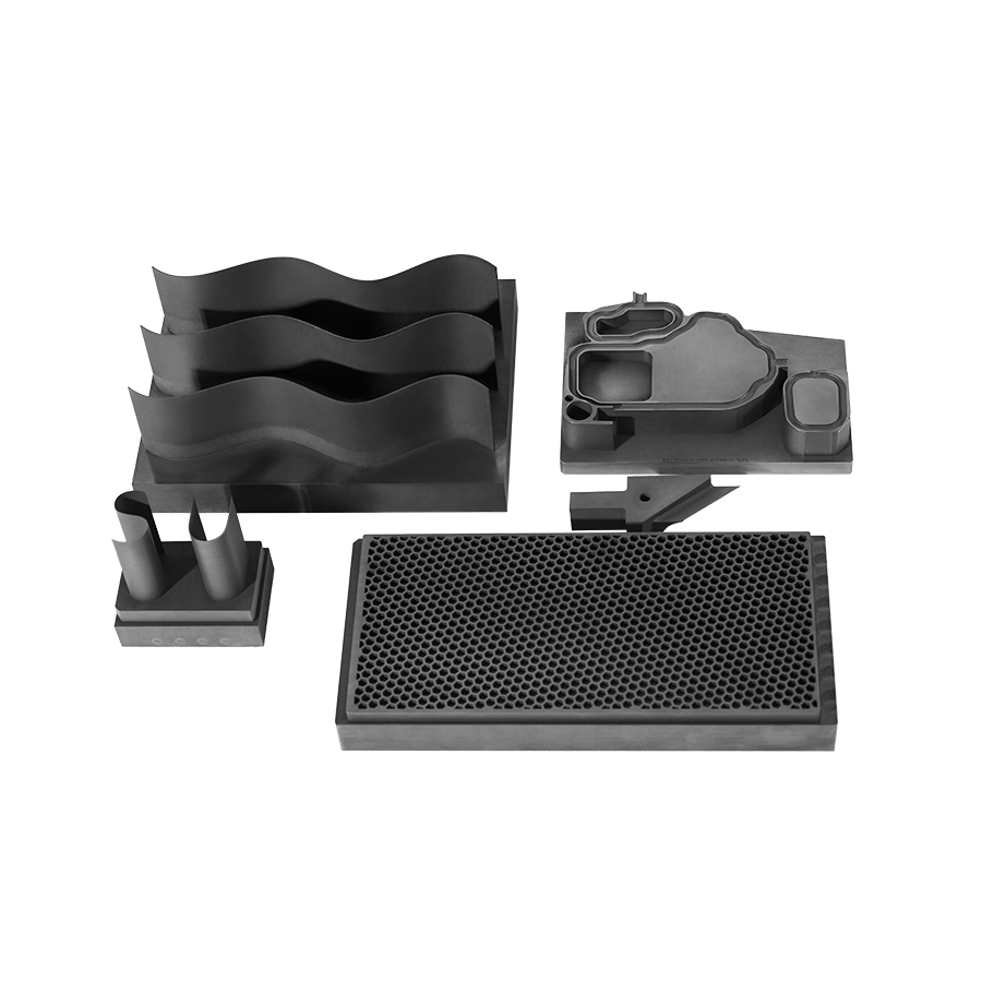
High-quality graphite CNC machining relies heavily on programmed tool paths. You cannot simply load a metal-cutting program and expect good results. Programmers must tailor every parameter to accommodate graphite's structural fragility.
Milling direction represents the most critical parameter for edge control. Climb milling remains absolutely mandatory. In conventional milling, the cutting edge enters the material at zero thickness and pushes outward toward the edge. This outward pushing force rips the fragile graphite grains apart, blowing out the edge.
Climb milling reverses this dynamic. The tool enters the material at maximum thickness and exits at zero thickness. More importantly, climb milling directs the cutting forces inward. It compresses the graphite into its own solid bulk structure. This inward stabilization prevents edge fracture entirely.
Table 1: Machining Approaches for Brittle Materials
| Milling Technique | Force Direction | Impact on Graphite Edges | Recommended Usage |
|---|---|---|---|
| Conventional Milling | Outward toward the part edge | High risk of fracture and blowout | Never recommended for graphite edges |
| Climb Milling | Inward into the bulk material | Compresses and stabilizes the edge | Mandatory for all finishing passes |
Calculating the correct feeds and speeds requires balancing thermal dynamics and physical pressure. We recommend utilizing high spindle speeds combined with moderate feed rates. This combination maintains a low, consistent chip load.
Chip load dictates how much material each cutting edge removes per revolution. If your chip load runs too high, pressure builds up against the cutting edge rapidly. This localized pressure fractures the material. Conversely, if your feed rate drops too low, the tool rubs against the abrasive graphite without cutting. Rubbing destroys the expensive diamond coating through excessive friction.
How the tool enters and exits the material dictates corner survival. Plunging a tool straight down into the Z-axis creates massive shock. Always use ramping strategies. Ramping introduces the tool into the material at a shallow angle, distributing the cutting force gradually.
Exit strategies require similar care. When a tool exits a cut, it loses the structural support of the surrounding material. Reduce the feed rate significantly right before the tool exits a corner. Slowing down prevents corner breakout by reducing the kinetic energy transferred into the fragile edge.
Many engineers overlook environmental controls when diagnosing edge defects. However, dust management plays a central role in surface integrity. Cutting graphite generates clouds of microscopic, highly abrasive powder.
If you fail to evacuate this powder, you trigger an abrasive feedback loop. The loose graphite particles remain trapped in the cutting zone. As the spindle rotates, the cutting tool recuts these loose particles continuously.
This trapped powder acts like a high-speed grinding compound. It aggressively strips the diamond coating from your tools. Simultaneously, the trapped powder gouges the surface of your component. This destroys both the tool edge and the final surface finish, leading directly to dimensional failures and chipped corners.
Managing this requires specialized infrastructure. Standard shop vacuums fail to capture fine graphite particulate. You need high-velocity extraction systems. These industrial vacuums must position their intake nozzles directly at the spindle head.
The extraction velocity must exceed the kinetic energy of the ejected particles. Evacuating the dust the exact millisecond it leaves the cutting zone ensures a clean tool path. Clean tool paths keep your PCD tooling sharp and your edges pristine.
A common mistake involves applying liquid coolant to wash away the dust. Graphite must remain strictly machined dry. Introducing liquid coolants creates a catastrophic chemical and mechanical reaction.
The fine graphite powder mixes with the liquid coolant to create a highly abrasive slurry. This thick paste bypasses standard machine seals. It infiltrates the CNC machine's linear guide ways and ball screws, destroying the equipment from the inside out. Furthermore, graphite features a naturally porous structure. Liquid coolants absorb deep into the material pores. This trapped moisture compromises the component's thermal properties and ruins its performance in high-temperature environments.
Choosing the right vendor for custom graphite machining prevents catastrophic project failures. You cannot treat graphite fabrication like standard metalworking. You must evaluate potential partners based on their specific material expertise and dedicated infrastructure.
Buyers must ask potential vendors targeted questions regarding their facility setup. The most important question is: "Are your machines exclusively dedicated to graphite?"
If a vendor machines steel or aluminum on the same CNC equipment used for graphite, cross-contamination becomes inevitable. Residual cutting oils from metalworking will contaminate your porous graphite components. Dedicated graphite facilities maintain isolated environments to protect material purity.
Investigate how vendors handle material yields. Reputable vendors account for inherent chipping risks in their pricing models. They calculate realistic raw material yields based on the geometric complexity of your design.
If a vendor promises perfect yields on fragile designs without explaining their mitigation strategy, they lack experience. Transparent partners will discuss potential failure points openly. They will explain how they order extra raw material to guarantee they meet your final delivery quantities.
Verifying exact tolerances on complex custom graphite components requires specialized metrology equipment. Standard inspection methods often cause the exact damage they intend to detect.
Inspectors frequently use mechanical touch probes on traditional Coordinate Measuring Machines (CMMs). The physical force exerted by a ruby-tipped probe easily fractures thin graphite walls during inspection. You must verify your vendor utilizes non-contact measurement systems. Optical comparators, laser scanners, and vision-based CMMs measure tight tolerances safely. They verify dimensional accuracy without ever inducing mechanical damage to the part.
When reviewing bids, look beyond the bottom line. Prioritize partners who demonstrate documented processes for tool wear tracking, dust control, and non-contact inspection. Vendors offering the lowest per-part bid typically lack the expensive PCD tooling and high-velocity extraction systems required for success. A cheap bid usually results in delayed deliveries, high rejection rates, and compromised component performance.
Edge chipping is not an inevitable reality of graphite machining. Rather, it serves as a glaring symptom of misaligned manufacturing processes. When chipping occurs, it usually points to incorrect tooling selections, aggressive cutting parameters, or inadequate environmental controls. By understanding the abrasive nature of graphite and demanding specialized machining environments, you can eliminate these defects completely.
Achieving flawless edges requires discipline. You must utilize PCD tooling, program optimized climb milling paths, and maintain aggressive dust extraction. We encourage buyers to proactively manage these variables. Request a consultation or a technical review of your CAD files before prototyping begins. Engaging an experienced machining partner early helps identify potential chipping risks in your design, ensuring your final components meet the most demanding operational standards.
A: The minimum thickness depends heavily on the specific graphite grade (grain size) and the PCD tooling utilized. Under optimized CNC conditions, walls and edges as thin as 0.010" (0.25mm) are highly achievable without fracturing.
A: Yes. Ultra-fine grain (isostatic) graphite holds sharp edges significantly better than medium or coarse-grain grades. The dense, uniform structure provides the necessary strength to withstand cutting forces without localized crumbling.
A: This usually traces back to utilizing standard metal-working parameters. Vendors often extend tool life too long to save costs, which causes dull edges to push and fracture the material. Poor dust extraction leading to abrasive wear also drives up scrap rates.


